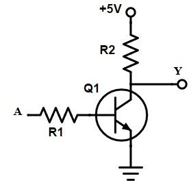
Not Gate Circuit Diagram Using Transistor
Gate circuit transistor logic inverter using truth table Nor gate circuit diagram transistor transistors using two electrical4u parallel junction connected bipolar shown basic below made What is not gate inverter, not logic gate inverter circuit using transistor
Very Large Scale Integration (VLSI): Understanding Logic gates at
Designing or gate circuit using transistor Very large scale integration (vlsi): understanding logic gates at Designing not gate using transistors
Transistor open gate
Gate transistor using circuit diagram improved schematic designing circuits versionNand circuit implementation transistors Logic gates using transistor – not, and, or » pija educationTransistor transistors diode circuitdigest kumar manoj diodes.
Transistor logic vlsi integrationNor gate: what is it? (working principle & circuit diagram) Transistor gate npn logic circuitsTransistors transistor implementation.


transistors - Implementation of NAND gate

NOR Gate: What is it? (Working Principle & Circuit Diagram) | Electrical4U

LOGIC GATES USING TRANSISTOR – NOT, AND, OR » PIJA Education

Designing NOT Gate using Transistors

Transistor Open Gate

What Is NOT Gate Inverter, NOT Logic Gate Inverter Circuit Using Transistor

Very Large Scale Integration (VLSI): Understanding Logic gates at